
Before presenting my paper on some interesting observations of the past few years it is necessary to first present a short description of polarity of electromagnetic fields.
Introduction
One of the problems that the EAV practitioner sometimes finds is that all measurement values on the Control Points and the Terminal points are exceptionally high with or without indicator drops. This pattern of measurements is what I call a “chaotic” measurement picture. It does not mean that the patient is ill, but that the potential for illness exists. Typically, geopathic stress and electromagnetic stress produce such a picture. This picture appears to be a result of reversed electromagnetic polarisation.
Electromagnetic Fields and Polarisation
First, let us define an electromagnetic field: An electromagnetic field is a field produced by moving electrically charged particles. It is one of the four fundamental forces of nature.
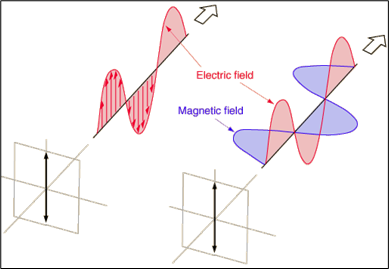
The electromagnetic field is a combination of an electric field and a magnetic field. The electric field is produced by stationary charges and the magnetic field by moving charges. The electrical field contains electrical energy. Energy density is proportional to the square of the field amplitude. Disturbances in the electromagnetic field are called photons and photon particles represent a disturbance in the electromagnetic field. Electromagnetic interactions arise from the exchange of photon particles. Since biological organisms communicate internally through photons there must therefore be electromagnetic interactions arising from the photon activity, and the photon activity must arise from disturbances in the electromagnetic fields. In this sense the electromagnetic field can be thought of as an information field.
Matter is made up of atoms and molecules. In living matter the atoms and molecules are continually moving. Also, the electrons of each atom and molecule are constantly in motion. Thus, the organism is giving off (and sensitive to) an infinite number of electromagnetic information fields. Some of these fields are life-sustaining (healthy) and some are detrimental to life (harmful). It is my suggestion that this is what we are indirectly observing and measuring when making an EAV, Vega or VRT diagnosis.
At present we are unable to display these minute fields in the form of wave information on a computer screen because the signal-to-noise ratio is too high. In other words, the noise produced by the electronic circuitry of the computer (or oscilloscope) is much greater than the signal that we wish to observe. This has the result of masking the desired signal. However, Dr. Cyril Smith of Salford University, UK, has suggested that biological organisms may be able to read through the noise and the human organism may be sensitive to near quantum fluctuation levels of energy, which is about the smallest level of energy imaginable. Undoubtedly, in the future we will be able to directly display and analyse these signals.
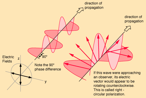
One of the curious features in chemistry is that of stereo-isomers where the molecular structure of two substances appears to be identical, except that one molecule is the mirror image of the other. There are some chemicals that have an identical molecular structure when written as a chemical formula, but if the structure is represented diagrammatically one structure is a mirror image of the other. The curiosity is that although they outwardly appear to be the same substance, the chemical properties differ to the extent that it is not possible to predict the chemical behaviour of the mirror image from knowledge of one of the substance. For example, lactic acid formed in the muscles can exhibit a “dextro” structure that is easily metabolised by the body; it can also form as “laevo” lactic acid, which is not easily metabolised and produces muscle cramps. A similar situation occurs with electromagnetic fields. This is a phenomenon known as polarisation. There are two kinds polarisation: linear and circular.
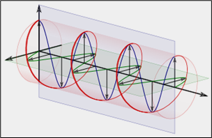 Left Polarised Field
(from the point of view of the receiver)
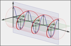 Right Polarised Field
(from the point of view of the receiver)
The characteristic that we are interested in is circular polarisation. With a circular polarised antenna the plane of polarisation rotates in a corkscrew pattern making one complete revolution per wavelength. A circular polarised wave radiates energy in horizontal and vertical planes and in every plane between. In radio engineering there is no signal loss with a circular polarised antenna and there is a very wide frequency band.
So what has this got to do with BioResonance? Well, it appears that biological signals are polarised both clockwise and anticlockwise. In the late 1970’s a brilliant Ph.D. student studying under the guidance of the well-known biophysicist Dr. Fritz-Albert Popp, suggested that polarised signals might play an important role in biology. The name of the student was Ludger Mersmann. (Sadly, he is now dead). Mersmann went on to design a suitable antenna for detecting such signals that could be used with BioResonance instruments. The rotation test – or Spin Tester – is a conical antenna wound in a clockwise or anti-clockwise direction. A conical antenna is sensitive to a wide range of frequencies, which also has the property of providing a slight amplification to the signal. The antenna is wound from the centre outwards. Thus, the LD spiral is anti-clockwise when traced from the centre towards the periphery, whilst the RD spiral is clockwise from the centre outwards. The RD spiral is sensitive to dextro rotation signals and the LD spiral is sensitive to laevo signals.
Dr. Franz Morell, working with this antenna (Spin Tester) made some very important observations. He discovered that almost all toxic agents such as bacteria, waste excretions, chemical toxins, etc. have a laevo or counter-clockwise field rotation while biologically supportive agents have a dextro or clockwise field rotation. Thus, body fluids that contain waste materials, for example urine, should have a laevo rotation, while vital fluids such as blood should have a dextro rotation.
In many cases these polarised fields can become reversed. If BioResonance treatment is given without first correcting polarisation reversals then results are usually disappointing. Either there is little or no effect, or any benefits of treatment are short lived.
The four biological products to test are blood, saliva (both dextro or RHS); urine, faeces (LHS.). The situation can arise where more than one product has reversed polarisation. It is probable that the more products reversed the more serious the illness is. Cancers will invariably show reversed polarisation of one or more fluids. It is important to note that reversed polarisation of blood and or other secretions does not indicate cancer but may indicate cancer potential.
Testing for field rotation
Place a spot of the fluid to be tested onto a piece of clean tissue or filter paper. One spot of fluid is sufficient. If testing blood, clean the skin surrounding the area to be lanced and then dry thoroughly so that the fluid from the cleaning swab does not contaminate the blood. Prick the skin and collect one spot of blood onto a piece of clean tissue.
- Blood is normally taken from a finger tip or from the earlobe.
- For saliva, ask the patient to moisten a small piece of tissue by placing it on or under the tongue.
- When testing urine a few drops of urine can be placed into a clean, sterile glass beaker.
- Faecal smears can be taken from toilet tissue, which is then wrapped in aluminium foil. The foil does not appear to interfere with the test.
- When the sample has been obtained, it should be placed into a clean sterile glass beaker to avoid contaminating the rotation tester.
Connect the rotation tester to the input of the measuring instrument (MT).
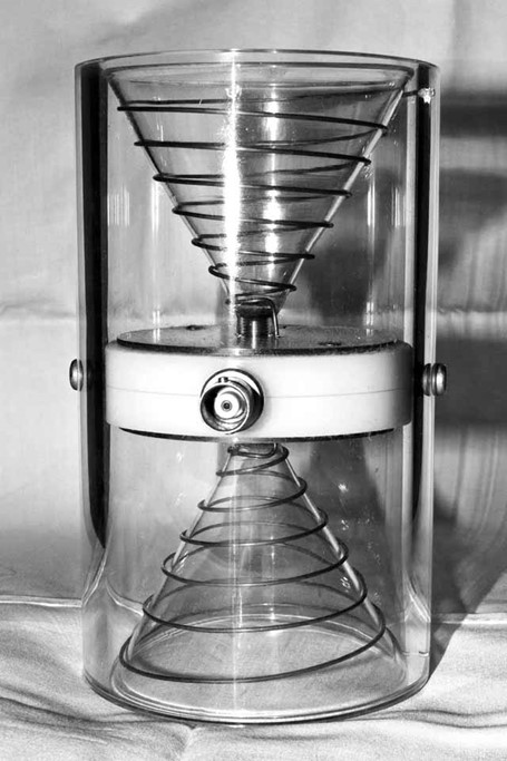 Rotation Test Antenna
This “Spin Tester” is connected by a cable to
the input (Med-Test) of the measuring instrument.
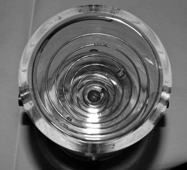
Clockwise Rotation
Looking from the centre outwards the antenna is wound clockwise.
Example
Let us suppose that we are testing for blood rotation. Place the beaker containing the spot of blood into the LD spiral and re-measure the terminal and or CMP’s. If the blood is laevo rotatory then most or all of the measurements should show improved measurement values in the direction of 50. This applies to both high measurements and to pathologically low measurement values.
If the beaker is now taken out and placed into the RD spiral the measurement values will revert back to the original values. We now have confirmation that the blood has a laevo rotation factor that requires correction.
In a very few cases it may be found that neither spiral improves the measurement values. In such cases it will be found that one of the other fluids has reversed rotation that is masking state of the blood.
Practical
- Collect a spot of fresh venous blood from a finger or earlobe onto a piece of clean tissue or onto a clean microscope slide.
- Place into RH spiral and use A inverse (A Bar, Ā or Inverted A)
- Re-measure points.
- If they have improved then the polarisation is normal.
- If there is no improvement then place the spot of blood into the LH spiral and re-measure.
- This should result in improved measurement values. In a few cases the results may be indeterminate. In such cases check other body fluids.
In all cases it is good practice to check the urine. When testing urine it should be placed into the LH spiral.
Correction
Correction is only required if there is a reversal in polarity. Leave the substance in the antenna that produced the correction. (For example, blood in LH spiral.)
- Use A inverse and connect output electrodes to all four quadrants (hand and foot electrodes).
- Give impulses of seven seconds with three second pause, 60 – 100 cycles.
- Before correcting, test for geopathic stress and advise the patient about protection.
- When the urine is reversed then test for electromagnetic stress.
Refinement to Testing and Treatment
This refinement can only be used with suitable instruments (BioResonance/MORA). It is a more refined treatment and suited to more experienced practitioners.
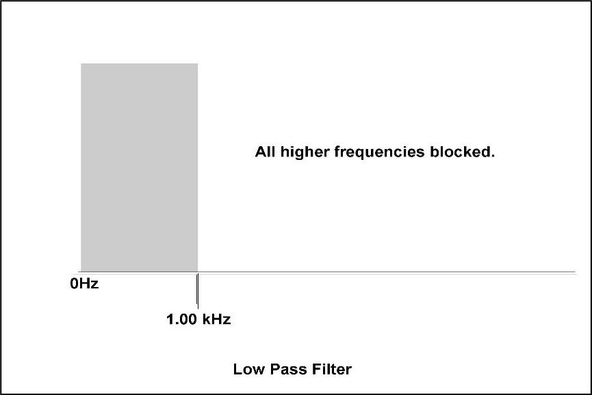
A low pass filter allows frequencies up to a set limit to pass through, but blocks any frequencies above that limit. For example, if set to 1.0 KHz (1000 Hz) then all frequencies below 1.0 KHz will pass through, but frequencies above 1.0 KHz will be blocked.
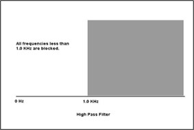
A high pass filter is the reverse. All frequencies above the set limit will pass through while frequencies below the limit will be blocked. Thus, if the limit is set at 1.0 KHz all frequencies above will pass but frequencies below 1.0 KHz will be blocked.
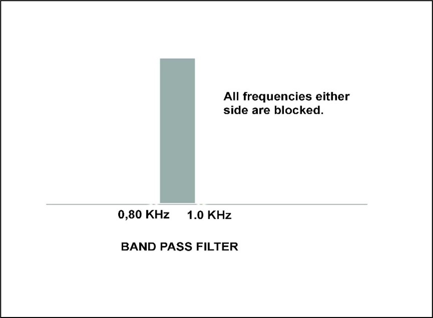
A Band Pass filter will block frequencies either side of the upper and lower set limits. For example, if the lower limit = 0.8 KHz and the upper limit = 1.0 KHz then only frequencies in the range 0.8 – 1.0 KHz will pass through.
The use of limit filters allows us to “tune” the treatment more precisely to the patient.
Example
Using a blood spot and the polarisation antenna, measure a point e.g. value = 90.
Set Low Pass to 1.0 KHz. Value now measures 64. This indicates that the sensitive frequency range is 1.0 KHz or less.
Set High Pass to 1.0 KHz. Value measures 90. There is no change. The precise correction frequency must, therefore, be less than 1.0 KHz.
Set High Pass to a value less than the Low Pass (in this example set to 0.95 KHz). Measurement value is now 54.
The conclusion is that the correction frequency lies between 0.95 and 1.0 KHz. The Band Pass filter is now used set at these limits. Measurement is stable at 50. This is now the optimum frequency range for treatment.
If the instrument allows, similar adjustment can be made for signal amplitude. This provides further fine tuning. In this way by using frequency limits and signal amplitude, treatment can be made highly specific for the patient.
(Note: the frequency-amplitude combination can be used when giving normal treatment without the use of a polarising antenna. However, basic therapy is significantly improved when such fine-tuning is applied.)
Interesting Case Application.
A patient presented who was fundamentally in good health. All control measurement points were stable with values ranging between 50 and 60. She produced eight different brands of vitamins C and wished to know which was the best. Each brand was placed in turn on the test plate. Of the eight, seven samples made the measurement values worse. Only one improved some values. Further testing revealed that seven bad ones all exhibited LH polarisation. The one good one showed RH polarisation.
A Japanese experiment on characteristics of growth and development of plants subjected to right polarised microwaves and laser radiation has been shown to alleviate biological efficiency.
The question therefore arises: is biological health and efficiency a characteristic of RH polarised signals and disease characteristic of LH polarised signals?
Recognising Geopathic and Electromagnetic Stress
Presenting symptoms will often include sleep disturbances: difficulty in getting to sleep, restless sleep, restless leg syndrome, waking at night, excessive dreaming, sometimes a deep sleep but waking unrefreshed, fatigue. There may also be mood swings such as irritability, feeling emotionally low but for no apparent reason. When questioned, patients will frequently respond that these symptoms describe them perfectly.
If using the “VRT” test ampoules, geopathic or em stress will test positive. EAV testing will reveal that most or all of the nail points measure 80 scale points or more, with or without an indicator drop. Most or all of the CMP’s will also measure very high. If one observes any of these patterns then the blood and/or urine rotation should be tested. One or both will be found to have reversed, i.e. blood will test as LH rotation and urine as RH rotation. The first treatment must be to correct the rotation factor in order to bring stability to the body. Only after such correction can reliable test data be taken.
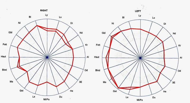
Graph 1 Geopathic Stress
Graph 1: The first thing to look at is the overall pattern of measurements. It is immediately noticeable that every measurement value is considerably outside the normal range (50-64). Many of the values also show indicator drops. Any pattern similar to this should immediately alert the practitioner to the possibility of geopathic or electromagnetic stress. This should be confirmed using the “VRT” test ampoules: Silicea D60 (geopathic stress); Lithium carb. D60 (geopathic stress); Phosphorus D60 (em stress). In this example, Silicea gave no indication but Lithium carb. returned a positive indication. When a positive indication of geopathic stress is found then the blood rotation should be tested. It will invariably show as Left rotation when using the rotation test. This patient was tested and treated in February 2011.
Perhaps the efficacy of such treatment is summed up by the following e-mail received from a patient about three days after the treatment:
“You are an amazing Man – I feel bloody marvellous. Long may it continue. Grateful thanks.”
 An Exclusive Article for Affiliates
From THE BRIDGE Newsletter of OIRFZ
Published December 2013
© Copyright 2013, Dr. Tony Scott-Morley, UK
Director’s Note: There is a long list of training and educational materials including books, reports, manuals, videos and DVD’s available through OIRF concerning BioResonance Therapy, MORA Therapy, EAV testing, Vega Testing and homeopathy. Private training sessions can be arranged with each of the OIRF Board of Medical Advisors, and OIRF sponsors and participates in seminars, conferences and workshops on all of these topics. Contact OIRF offices for further details and information or visit our website

")
